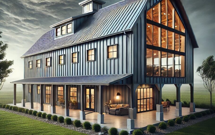
Floor-to-ceiling glass has become one of the defining features of modern barndominium design. Owners want panoramic views, daylight-filled interiors, and seamless transitions between indoor and outdoor spaces. But behind that minimalist aesthetic lies serious engineering. When you replace a conventional framed wall with tall, uninterrupted glazing, you’re asking the glass and its connections to perform structural work—often in a steel frame that moves, flexes, and expands.
In barndominiums built from pre-engineered metal systems, movement is not a theoretical concern. It’s a reality. Wind loads, thermal expansion of steel, foundation settlement, and even roof diaphragm action introduce frame deflection. The structural silicone joints bonding glass to metal must be designed to accommodate these forces safely and durably.
This article walks through the engineering logic behind structural silicone glazing (SSG) in barndominiums, focusing on how to calculate joint sizes for floor-to-ceiling glass installed in a moving frame. We’ll stay grounded in practical field realities—because good glazing design doesn’t stop at formulas.
Understanding Structural Silicone Glazing in a Barndominium Context
Structural silicone glazing uses high-performance silicone sealants to bond glass directly to a metal frame without traditional mechanical pressure plates or exterior caps. Instead of relying solely on clamps, the cured silicone acts as a structural adhesive, transferring wind loads from the glass to the supporting frame.
In a conventional commercial curtain wall, frame deflection limits are tightly controlled. In barndominiums, especially those derived from agricultural steel buildings, deflection tolerances may be looser. That makes joint design even more critical.
The silicone must:
- Transfer wind load from the glass to the steel frame
- Accommodate thermal movement of both glass and steel
- Tolerate frame deflection under load
- Resist long-term environmental degradation
When floor-to-ceiling glass panels stretch 10 to 20 feet high, these requirements intensify. Joint sizing is no longer a guess—it’s an engineering exercise.
Step One: Determine the Design Loads
Before sizing any silicone joint, you must know the forces it will resist. For barndominiums, wind load is typically the governing factor.
Wind pressures are determined by:
- Geographic wind speed (per ASCE 7 or local code)
- Exposure category (open farmland vs. suburban shielding)
- Building height
- Panel location (corner zones experience higher pressures)
For example, in many central U.S. regions, design wind speeds may range from 115 to 140 mph. In coastal or tornado-prone areas, pressures can be significantly higher.
Let’s assume a simplified case:
- Glass panel: 6 ft wide × 14 ft tall
- Design wind pressure: 40 psf (positive or negative)
Total wind force on the panel:
6 ft × 14 ft × 40 psf = 3,360 pounds
That force must be transferred through the structural silicone along the panel perimeter.
Step Two: Understand How Load Transfers Through Silicone
Structural silicone joints typically run along the vertical edges (and sometimes top and bottom). For vertical load transfer under wind pressure, the critical dimension is the “bite” of the silicone—the contact width between the silicone and the glass/frame.
The basic engineering relationship for structural silicone in shear is:
Required Bite = Load per unit length / Allowable design stress
Most structural silicones have allowable design stresses provided by manufacturers, often around 20 psi (pounds per square inch) for long-term wind load applications. Always verify with product-specific data and testing requirements.
Now let’s distribute the wind load.
If the panel is supported on two vertical edges only, each vertical joint resists half the total wind load.
Total wind load: 3,360 lbs
Load per vertical edge: 1,680 lbs
Vertical edge height: 14 ft = 168 inches
Load per inch of joint:
1,680 lbs / 168 inches = 10 lbs per inch
Now divide by allowable stress (20 psi):
Required bite = 10 lbs/in ÷ 20 lbs/in² = 0.5 inches
So the silicone must have at least a 1/2-inch structural bite.
In practice, engineers typically increase this value for safety factors, tolerances, and long-term durability—often rounding up to 5/8 inch or 3/4 inch.
Step Three: Account for Frame Movement
Barndominiums use steel primary framing. Steel expands approximately 6.5 × 10⁻⁶ inches per inch per degree Fahrenheit. Over long spans, thermal movement becomes meaningful.
For example:
A 20-foot steel member experiencing a 100°F temperature swing:
20 ft = 240 inches
Movement = 240 × 6.5 × 10⁻⁶ × 100 ≈ 0.156 inches
That’s over 1/8 inch of movement purely from temperature.
Now consider:
- Wind-induced deflection
- Live load deflection from roof systems
- Foundation settlement
Unlike rigid commercial curtain wall systems, many barndominiums may allow L/120 or L/180 deflection limits rather than stricter L/240 or L/360 limits. That increased movement must be absorbed somewhere—and that somewhere is often the silicone joint.
This is where joint thickness matters.
Step Four: Determine Joint Thickness for Movement Capacity
Silicone joints must be thick enough to stretch and compress without overstressing the material. The thicker the joint, the greater its movement capability.
Typical structural silicone joint thickness ranges from 1/4 inch to 1/2 inch. Thicker joints allow more movement but may reduce structural stiffness. There is a balance.
Movement capability is often expressed as ±25% or ±50% of joint width, depending on the sealant.
If you expect total differential movement of 1/4 inch between glass and frame, and the sealant allows ±25% movement:
Required joint width = Movement ÷ 0.25
= 0.25 ÷ 0.25
= 1 inch
That’s a large joint. In practice, engineers reduce movement demands by:
- Improving frame stiffness
- Using setting blocks and mechanical supports
- Designing hybrid systems (structural + captured glazing)
The goal is to keep structural silicone primarily in shear, not excessive tension or compression.
Shear vs. Tensile Performance
Structural silicone performs best in shear. When wind pushes on glass, the bond line experiences shear stress parallel to the surface. This is ideal.
When frame deflection causes the joint to open or close excessively, tensile and compressive stresses develop perpendicular to the bond line. Silicone tolerates this—but only within limits.
For tall barndominium glazing walls, deflection compatibility must be evaluated carefully. If a steel beam above the glass deflects 1 inch under roof load, that movement will directly stress the top joint unless isolation detailing is included.
Engineering coordination between the metal building designer and glazing engineer is essential.
Glass Thickness and Its Role
The silicone joint doesn’t work alone. Glass thickness determines how much the panel deflects under wind load. Excessive glass deflection increases stress at the joint.
For tall barndominium installations, laminated tempered glass or insulated glass units (IGUs) are common. Engineering calculations must verify:
- Glass bending stress
- Edge stress
- Deflection limits (often L/60 or better for aesthetics)
If the glass is too thin, it will bow excessively, prying at the silicone bond. Increasing glass thickness reduces joint stress and improves long-term reliability.
Environmental Considerations in Barndominiums
Unlike urban office towers, barndominiums often sit in open rural exposures. Wind loads can be more severe. Dust, agricultural chemicals, and high UV exposure also impact sealant longevity.
Key considerations:
- Use structural silicone tested for UV resistance
- Ensure proper surface preparation (steel coatings must be compatible)
- Verify primer requirements
- Perform adhesion and compatibility testing
Steel frames often have high-performance coatings. Not all silicones bond equally to every paint system. Adhesion testing is not optional.
Field Tolerances and Real-World Conditions
Engineering calculations assume clean geometry. Field conditions rarely comply.
Consider:
- Steel fabrication tolerances
- Slab elevation variations
- Frame twist during erection
- Thermal expansion during installation
If your calculated structural bite is 1/2 inch, but field tolerances reduce it to 3/8 inch in places, your safety margin disappears.
Best practice includes:
- Designing with conservative joint sizes
- Using spacers to control bite depth
- Inspecting joint dimensions before sealant application
- Documenting quality control
Structural silicone glazing demands disciplined installation.
Redundancy and Safety Strategy
Relying exclusively on silicone for tall floor-to-ceiling glass in a flexible steel barndominium frame can be risky. Many successful designs incorporate redundancy:
- Mechanical retainers concealed behind mullions
- Dead-load support blocks at the sill
- Structural setting blocks
- Backup gaskets
Silicone handles wind shear; mechanical supports carry gravity loads. Separating these functions improves long-term reliability.
In hurricane-prone regions, impact-rated laminated glass may also be required. The joint must then accommodate not just static wind load but dynamic pressure cycling.
Movement Compatibility with Insulated Glass Units
When using insulated glass units, differential movement between outer and inner lites can introduce additional stress. The structural silicone typically bonds to the outer lite only.
Engineers must verify:
- Edge seal compatibility
- IGU edge spacer durability
- Thermal cycling effects
Large glass expanses facing south or west in a barndominium can experience intense thermal gradients. These cycles repeat daily, year after year.
Designing joint thickness generously is an investment in durability.
Practical Design Example Summary
Let’s summarize a conservative design approach for a tall barndominium glass wall:
- Determine wind pressure from code
- Calculate total load per panel
- Distribute load to structural silicone edges
- Compute minimum bite using allowable stress
- Increase bite for safety factor
- Evaluate frame deflection limits
- Size joint thickness to accommodate predicted movement
- Confirm glass thickness limits deflection
- Perform adhesion testing on coated steel
- Include mechanical redundancy
This method transforms a beautiful glass wall from a liability into a long-term asset.
Why This Matters in Barndominium Design
Barndominiums celebrate openness. Expansive glass walls blur the boundary between shop, home, landscape, and sky. But these buildings originate from metal systems engineered for efficiency, not always for delicate glazing interfaces.
When you introduce structural silicone glazing into a moving steel frame, you’re merging two engineering philosophies. That merge requires thoughtful detailing.
Done correctly, floor-to-ceiling glass in a barndominium can perform for decades. Done casually, it can fail in ways that are costly and dangerous.
The difference lies in respecting joint design.
Final Thoughts
Structural silicone joint sizing is not guesswork. It’s a disciplined process grounded in load calculations, movement analysis, material science, and field quality control.
In barndominiums, where steel frames move more than traditional concrete or rigid curtain wall systems, that discipline becomes even more critical. Wind load must be calculated accurately. Silicone bite must be sized conservatively. Joint thickness must anticipate movement. Glass deflection must remain within limits.
Most importantly, glazing engineering must coordinate with the structural engineer of record. When the steel frame, glass panel, and silicone joint are designed as a system—not as isolated parts—the result is both striking and safe.
Floor-to-ceiling glass defines modern rural architecture. Behind that elegance lies careful math, practical field awareness, and respect for movement. That’s advanced glazing engineering in the real world of barndominiums.